
Specifications
I) INTRODUCTION
This technical specification is an outline of the machining capabilities of Applied Laser Solutions Ltd; i.e. the laser machining, drilling and scribing of thick and thin film Alumina. This specification is intended for engineers and quality personnel, to help them understand and design substrates for laser processing. If your requirements fall outside this specification, then please contact Applied Laser Solutions Ltd. It is possible that your criteria could still be met.
II) LASER TOLERANCES
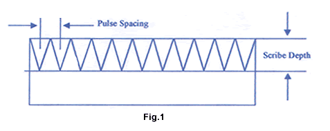
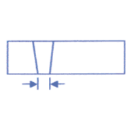
A) LASER SCRIBING (see Fig. 1)
1) Scribed pulse depth: 35 - 50% standard across all thicknesses
2) Pulse spacing: 0.14 - 0.17mm between each laser pulse
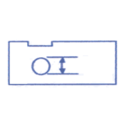
3) Scribed edge to feature: +. 1/-.05mm
4) Scribe line to scribe line: +/-.05mm
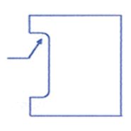
B) LASER DRILLING AND PROFILING
The tolerances specified below are standard tolerances, however tighter tolerances can be achieved, please contact us if your criteria are not met within these specifications.
* Length and Width
+/-.002" (+/-.051mm)

* Hole Diameter
+/-.0015" (+/-.0381mm)
* Medium Web Thickness
hole edge to another edge = substrate thickness
between adjacent holes = substrate thickness

* Corner Radii
minimum .006" (.15 mm)
Nb. To reduce the risk of microcracking and chipping, it is recommended that an internal radii is used in preference to a sharp corner
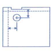
* Hole and Feature Location
+/-.002" (+/-.051mm) From any machined area to hole centreline
+/-.002" (+/-.051mm) From centre of scribeline to hole centreline
* Medium Hole Diameter
Single shot .003" (.06mm)
Drilled .004" (.1 mm)
* Narrowest Profiled Slot
0.004" (.102mm)
